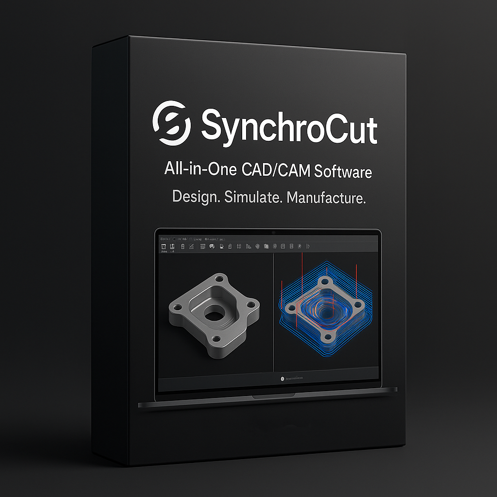
SynchroCut (CAD Mode) & (CAM Mode)
฿25,000.00
SynchroCut is a powerful, all-in-one CAD/CAM solution designed for precision and efficiency. Built from the ground up, it provides a seamless, intuitive workflow that takes your creative concepts directly to G-code, eliminating the compatibility issues and data loss common with using separate design and manufacturing programs.
Description
SynchroCut is a powerful, all-in-one CAD/CAM solution designed for precision and efficiency. Built from the ground up, it provides a seamless, intuitive workflow that takes your creative concepts directly to G-code, eliminating the compatibility issues and data loss common with using separate design and manufacturing programs.
From intricate 3D models to precise 2D patterns, SynchroCut’s robust design tools give you the creative freedom to build without limits. When your design is complete, the integrated CAM engine takes over. It intelligently analyzes your geometry to generate optimized, efficient toolpaths for milling, routing, turning, and more. With a clear, interactive simulation, you can verify every cut and movement before sending it to your machine, saving time, material, and preventing costly errors.
SynchroCut is the perfect partner for hobbyists, small shops, and custom fabricators who demand a streamlined, reliable, and powerful tool to bring their digital designs to physical reality.
Quick Guide: How to Use SynchroCut
This guide outlines the basic workflow from creating a design to exporting the final G-code for your CNC machine.
Step 1: Design Your Part (CAD Mode)
- Start a New Project: Open SynchroCut and create a new project file.
- Sketch Your Base: Select the sketching tool. Choose a plane (e.g., XY, XZ) and draw the 2D profile of your part using lines, arcs, circles, and rectangles. Use the dimensioning tool to ensure your sketch is precise.
- Create a 3D Model: Once your sketch is complete, use a modeling tool like Extrude to give it thickness or Revolve to create a cylindrical shape. You can continue to add or remove features like holes, fillets (rounded edges), and chamfers.
- Finalize the Design: Use the measurement and inspection tools to verify that all dimensions are correct. Save your part.
Step 2: Prepare for Machining (CAM Mode)
- Switch to CAM Workspace: With your model open, switch from the “DESIGN” workspace to the “MANUFACTURE” (or “CAM”) workspace.
- Create a Setup:
- This step defines your raw material (stock) and the part’s orientation.
- The software will typically create a stock box that is slightly larger than your model. You can adjust its size to match your actual material.
- Set the Work Coordinate System (WCS), which defines the “zero” point (X0, Y0, Z0) for the machining operation. This is often a corner of the stock or the center.
- Select a Machining Strategy:
- From the toolbar, choose the type of toolpath you want to create. Common choices include:
- 2D Pocket: To clear out material from an internal cavity.
- 2D Contour: To cut around the outside or inside edge of a profile.
- Drill: To create holes.
- 3D Adaptive Clearing: An efficient strategy for roughing out large amounts of material from a 3D shape.
- From the toolbar, choose the type of toolpath you want to create. Common choices include:
- Configure the Toolpath:
- Tool Selection: Choose a cutting tool (e.g., a 1/4″ flat end mill) from the tool library. Define its speeds and feeds (spindle speed and cutting feedrate).
- Geometry Selection: Select the faces, edges, or contours of your model that you want to machine.
- Heights & Linking: Define the clearance, retract, and cutting depths to ensure the tool moves safely and efficiently.
- Click “OK” to generate the toolpath. It will appear as a visual line over your model.
Step 3: Simulate and Export G-Code
- Simulate the Operation: Select your setup or the specific toolpath and click the “Simulate” button.
- This will open a new window showing an animation of the tool cutting away the stock material to create your part.
- Watch carefully for any collisions or incorrect cuts. You can enable “Stock” view and “Stop on collision” for better error checking.
- Post-Process to G-Code:
- If the simulation looks correct, close it and select the toolpaths you want to export.
- Click “Post Process”.
- In the post-processing dialog, select the correct post-processor for your specific CNC machine (e.g., GRBL, Mach3, Fanuc). This ensures the G-code is in the correct dialect.
- Click “Post” to save the
.ncor.gcodefile to your computer.
- Run on Your CNC: Transfer the generated G-code file to your CNC control software to begin machining your part.